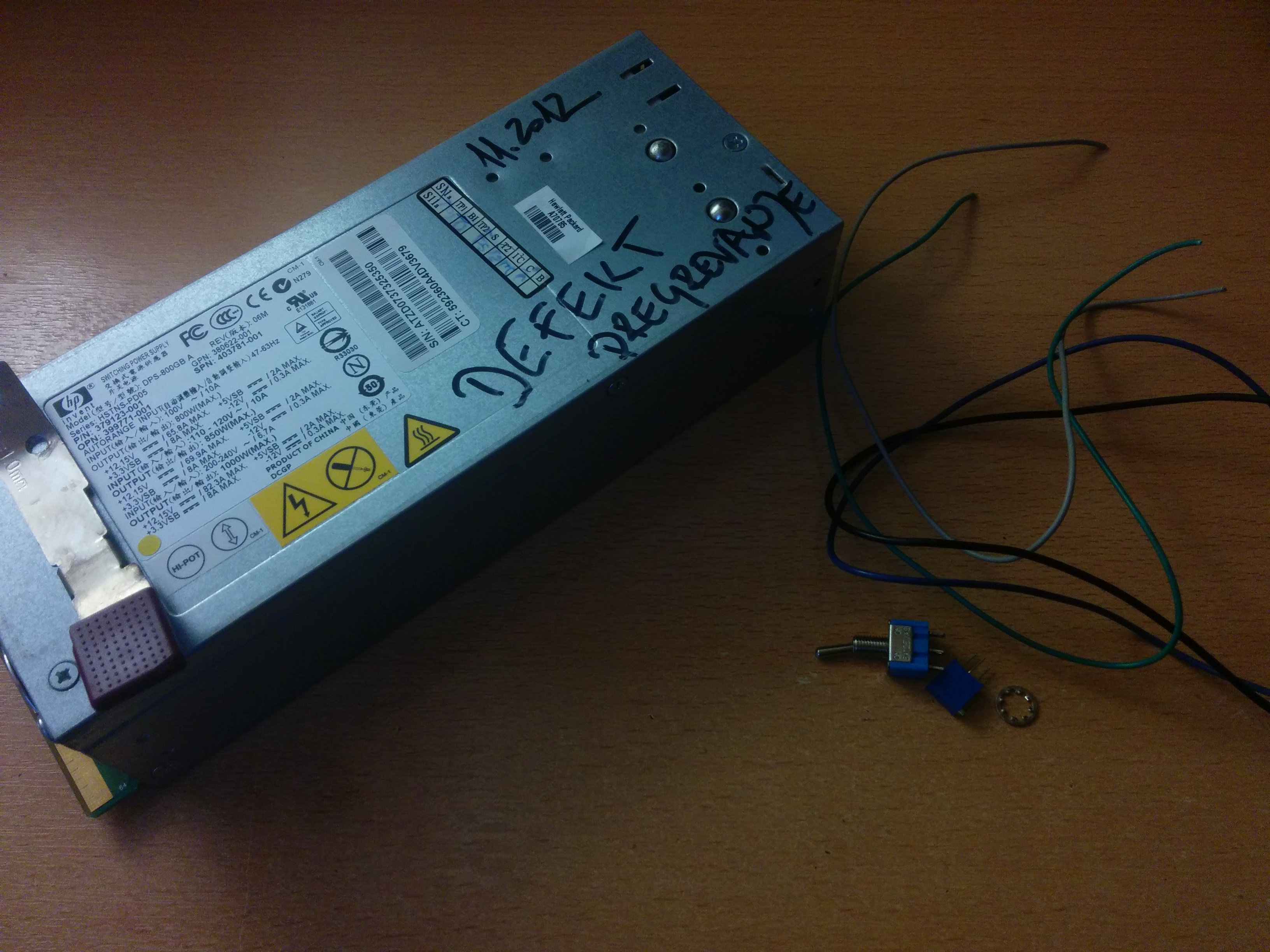
So a couple of weeks ago I got a HP DPS-800GB A server PSU that was thrown away due to “overheating”. So I decided to mod it into a standalone adjustable 12v-13v 1000W PSU. So here is how I modified mine and how you can mod yours 😉 .
Disclaimer: I am in no way, shape, or form responsible for your actions. If you burn down your house or hurt yourself don’t blame me. But anyway, happy modding.
What do you need?
Essentials:
- DPS-800GB A PSU (40€),
- 10kΩ potentiometer (almost free),
- 1 simple toggle switch (also almost free),
- Thin cables (just search around the house),
- Hot glue or any other strong glue that will not eat away plastic (7€)
- Soldering iron and some solder (15€ for a basic set).
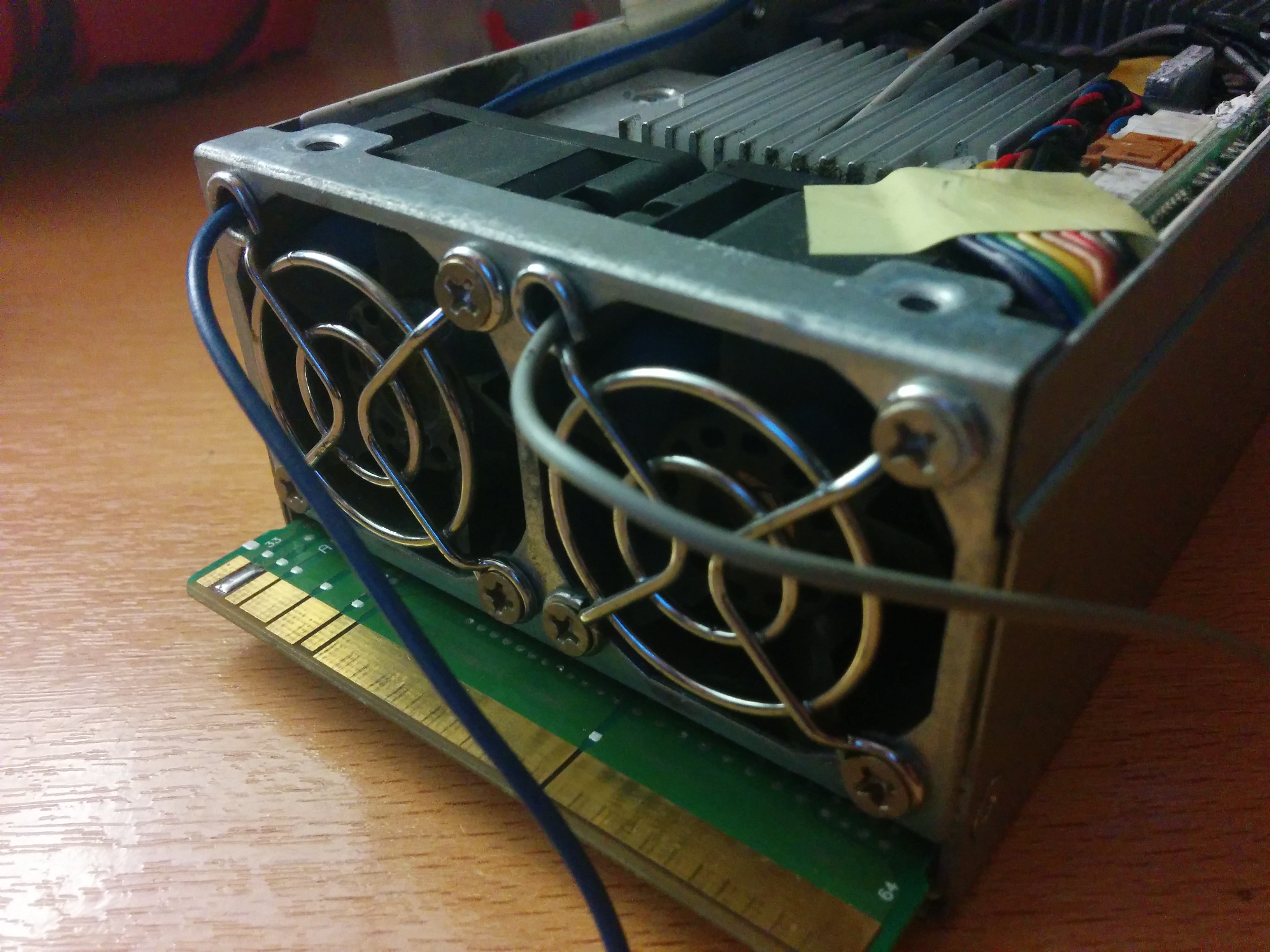
Picture of the needed parts:
Step by Step:
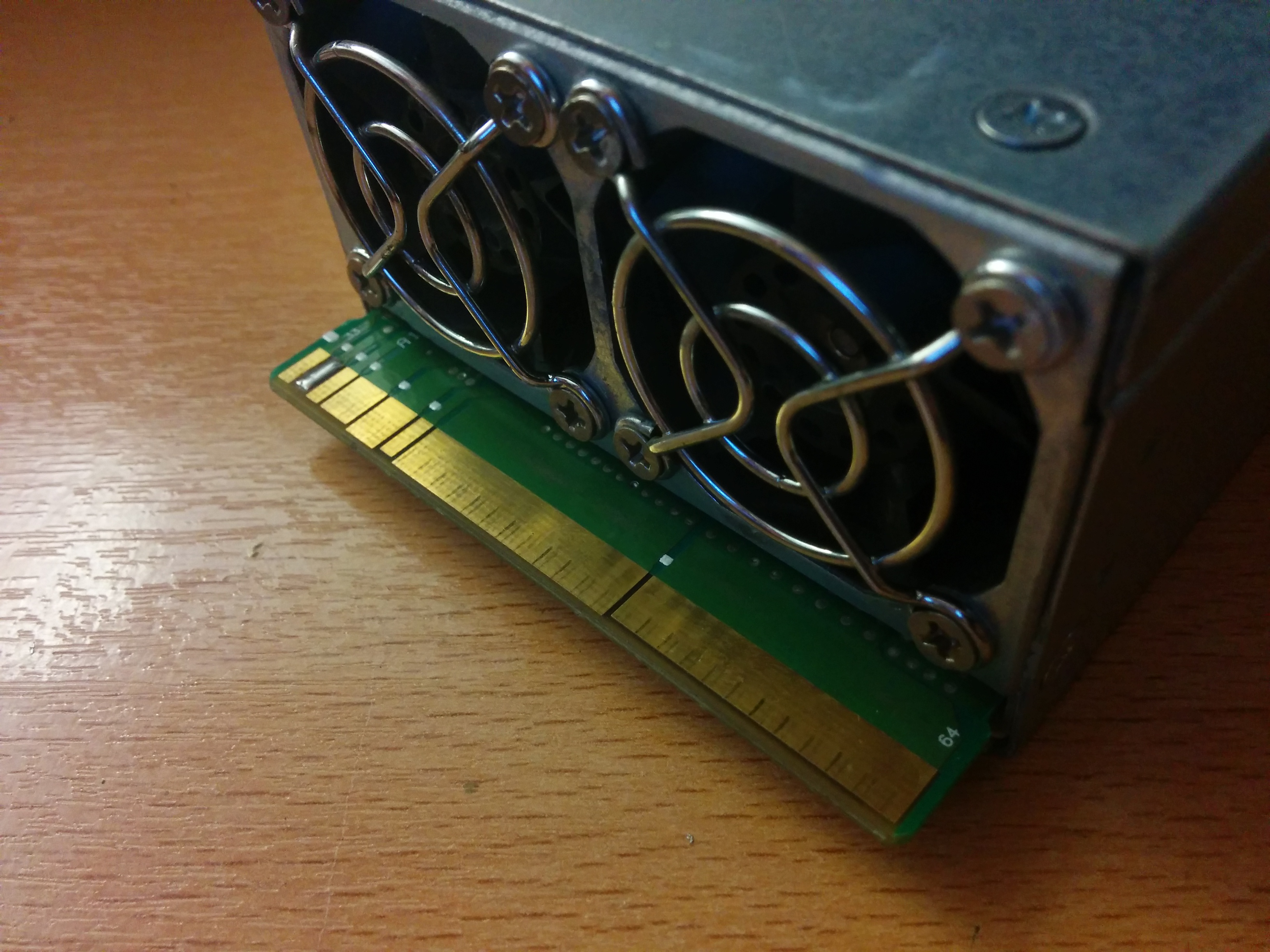
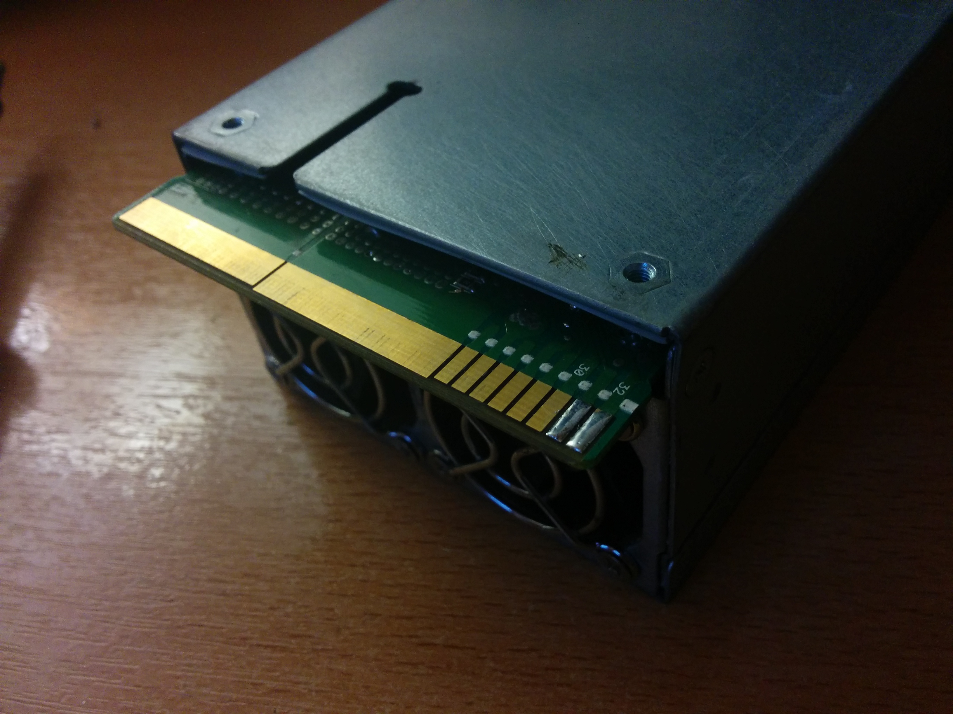
0.5 Remove the pull tab
On the picture above you can see the pull tab removed. Simply take of the cover of the PSU and rip it out with a screwdriver. We will need that hole for the switch.
1. Solder the correct pads
Note: I am basing this mod on information provided here.
2. Wire it up
Firstly wire up the switch like this. The orientation in this case does not matter.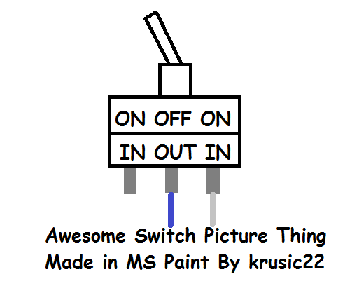
My switch has the ability to be turned off (not connect to any pin except the middle one). BUT this does not matter! Since we are only using one input it will turn on the power supply in only one position. TL;DL version: It will work with any switch if you connect it right.
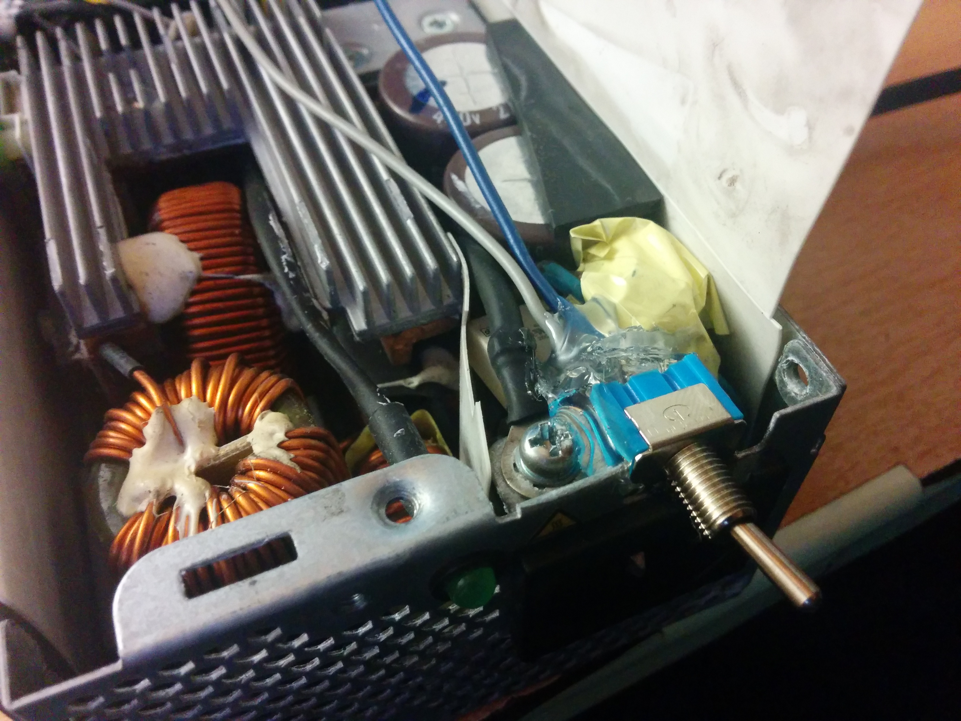
You can use the soldering iron to make a small hole for the switch to sit in (see: second picture). After the switch is in position in place glue it in place.
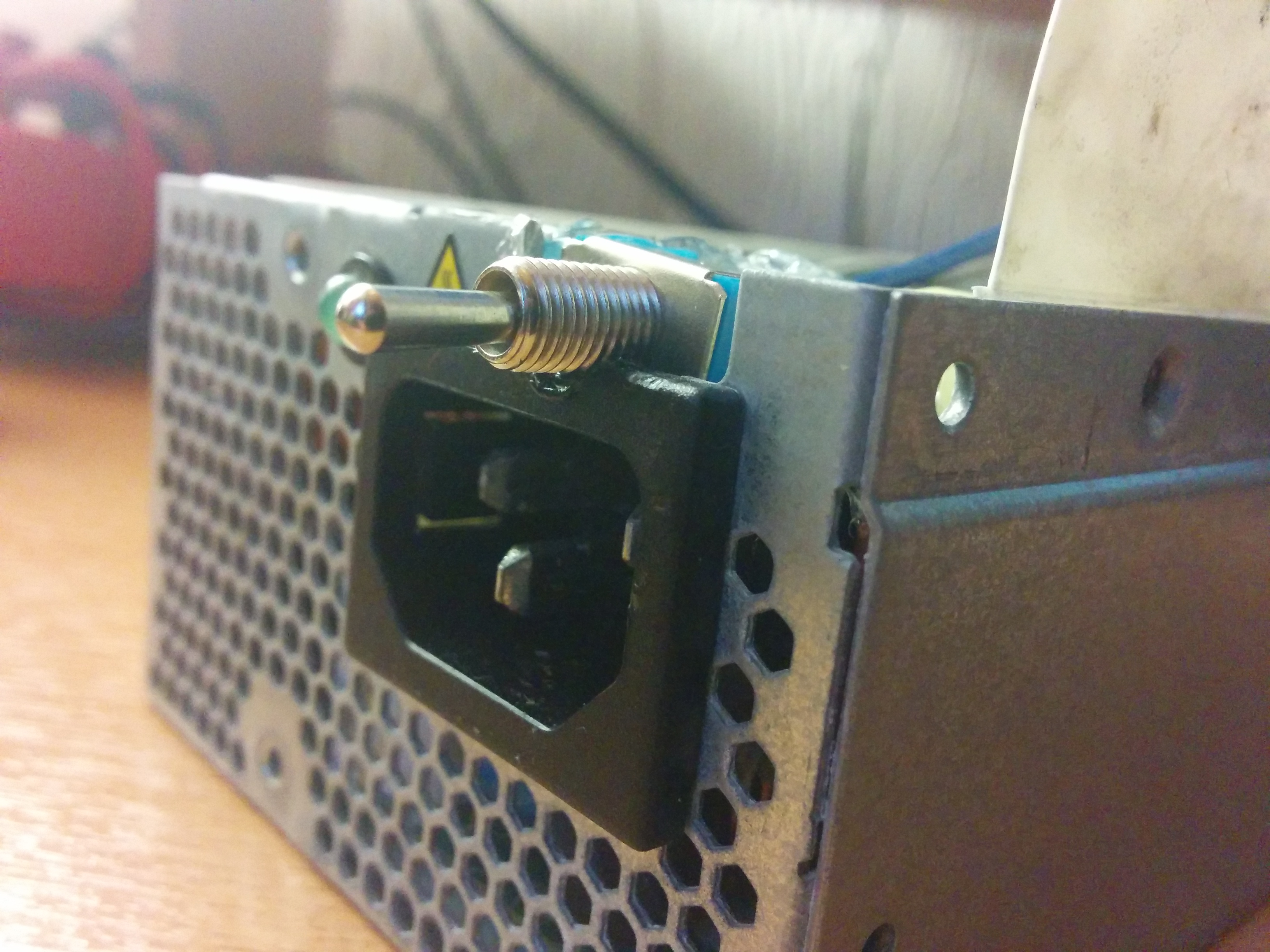
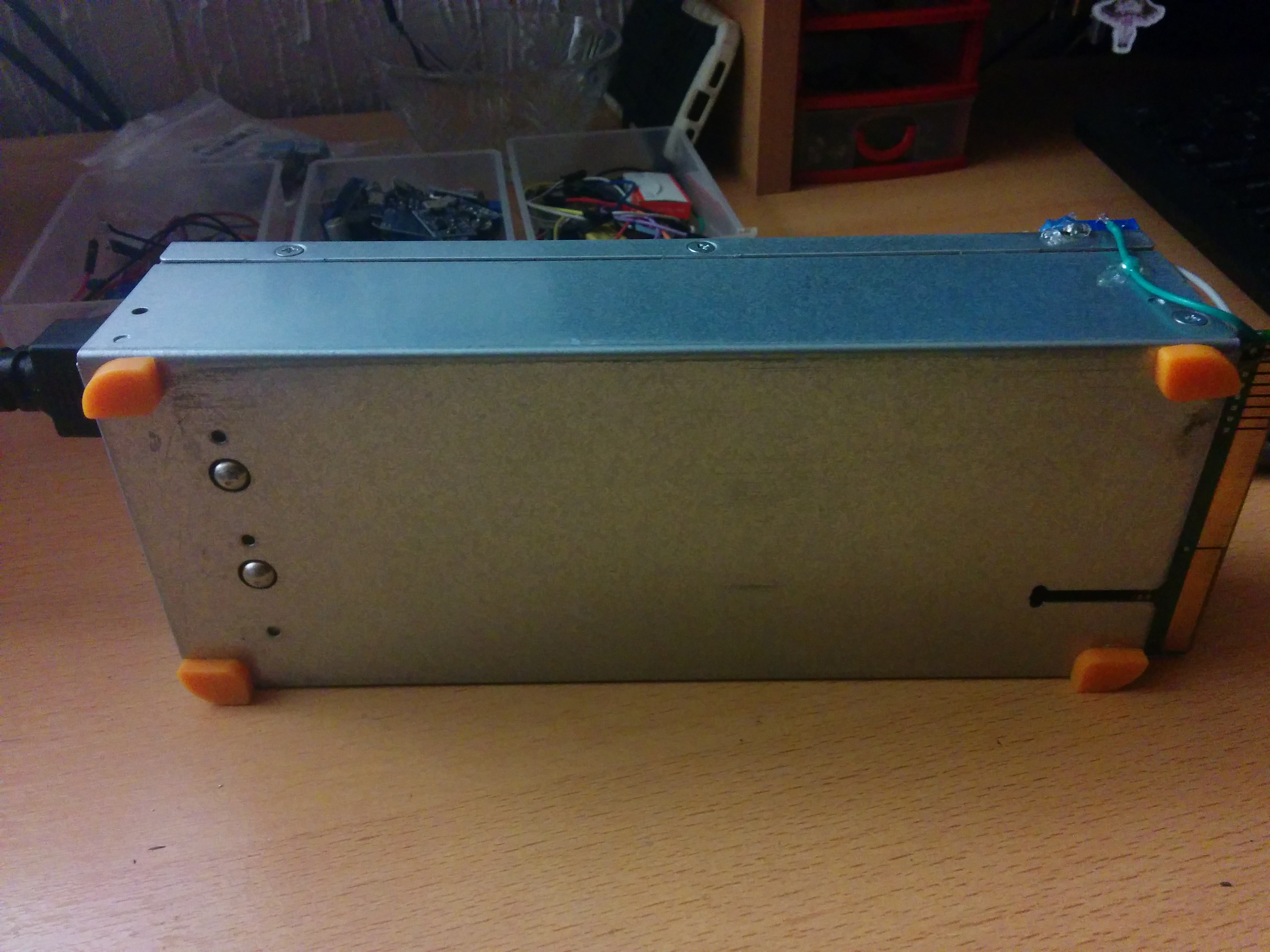
3. Route the wires outside
Technically we could connect the wires inside but I don’t want to take the risk of dissembling it. So simply remove the two screws (or one if you used thin wires) and route the wires outside.
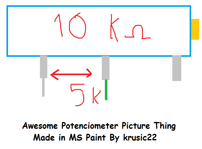
4. Attach the potenciometer
Adjust the potenciometer to 5k (middle). Attach the first pin to ground and the middle one to a wire (you can cut away the unused pin). Then glue it in place.
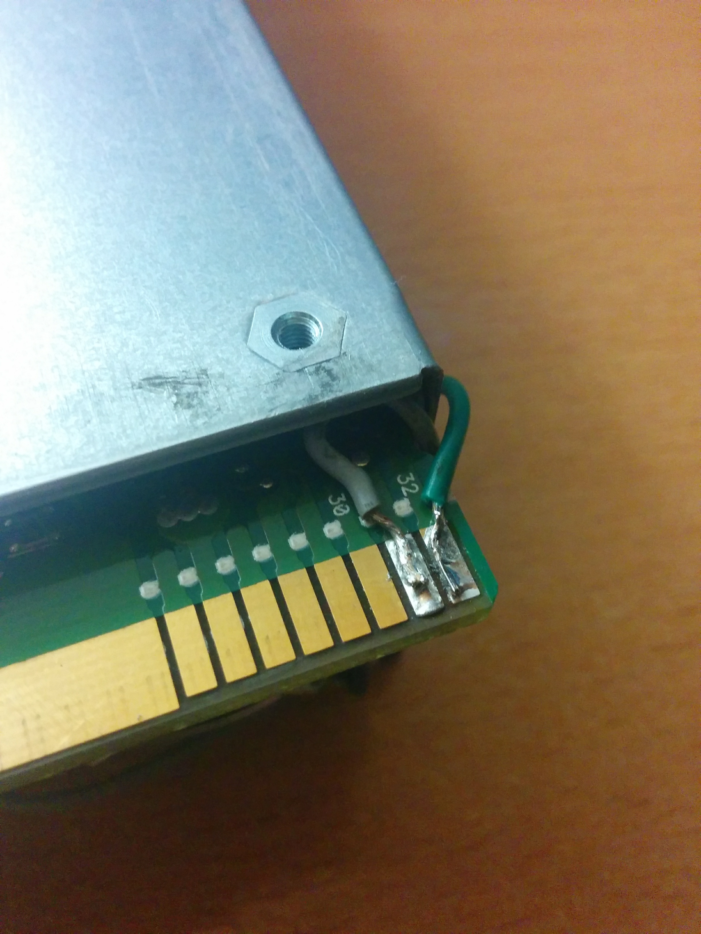
5. Final soldering
Connect the Blue wire (from the switch) to the second connection the top of the PSU (next to 33).
After that connect the Green cable (potenciometer middle) to the first pin (32) on the bottom. Since we use the casing as Ground we don’t need any additional wires for the potenciometer.
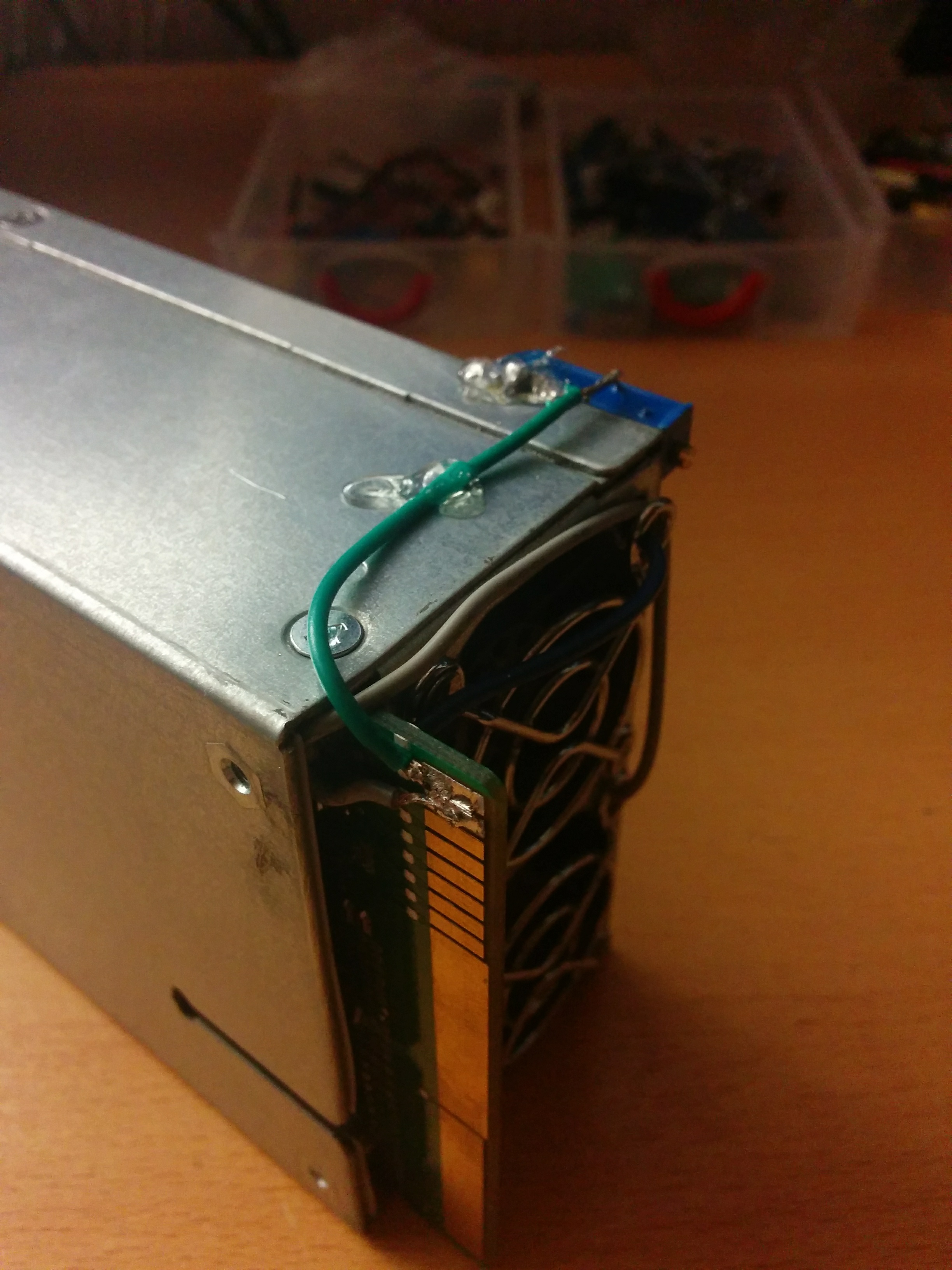
And on the end connect the Gray (from the switch) to the pin next to 32 on the bottom.